Observação: Neste artigo, LV significa Baixa Tensão, MT para Média Tensão, AT para alta tensão.
Para redes de distribuição de energia no exterior, projetos de novas energias e infraestrutura, Lv, Cabos MT e HV servem como meio central para transmissão de energia. Muitas falhas de projetos não decorrem da má qualidade do produto, mas seleção incorreta do grau de tensão ou compreensão insuficiente das lacunas estruturais e de teste entre esses tipos de cabos.
Da nossa experiência prática no suporte a vários projetos EPC no exterior, muitos compradores se concentram apenas na seção transversal do condutor, ignorando os requisitos de blindagem e testes vinculados às classificações de tensão. Isto leva à falha na aceitação do local e à quebra do isolamento do serviço. Este artigo cobre definições, construção, comparação, seleção, casos reais e perguntas frequentes para avaliação técnica por engenheiros e equipes de compras.
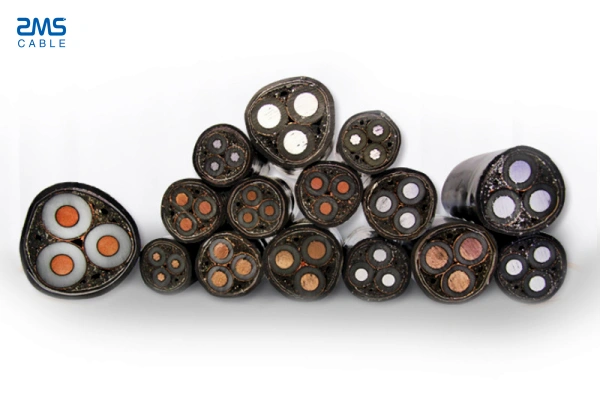
O que são LV, Cabos MT e HV?
Classificado de acordo com os padrões internacionais IEC, esses cabos são diferenciados principalmente pela tensão nominal. Suas estruturas internas ficam mais complexas à medida que a tensão aumenta.
Lv (Baixa Tensão) Cabos
- Classificação de tensão: ≤1kV, normalmente 0,6/1kV
- Construção típica: Condutor (cobre / alumínio) + isolamento + haste + fita adesiva + bainha externa. A armadura é opcional. Nenhuma blindagem semicondutora ou metálica é necessária.
- Características: Construção simples, instalação flexível e menor custo de aquisição. Projetado para distribuição de energia do usuário final para edifícios e equipamentos.
- Aplicativos: Fonte de alimentação do edifício, conexão de equipamentos industriais, energia temporária do site, distribuição comunitária residencial.
MV (Média Tensão) Cabos
- Classificação de tensão: 1 kV-35kV, classificações comuns: 6/10 kV, 8.7/15 kV, 12/20 kV, 26/35 kV
- Construção típica: Condutor + tela semicondutora condutora + Isolamento XLPE + tela semicondutora de isolamento + escudo de cobre metálico + camada de cama + (armadura opcional) + bainha externa. As telas semicondutoras internas e externas, além da blindagem metálica, são obrigatórias para homogeneizar os campos elétricos e evitar falhas de isolamento causadas por descarga parcial..
- Características: Requisitos rigorosos de fabricação. O teste de descarga parcial é obrigatório na fábrica. Adequado para fornecimento de energia a média distância.
- Aplicativos: Principais redes de distribuição urbanas, circuitos coletores de parques eólicos e solares, grandes parques industriais, alimentadores de saída da subestação.
Hv (Alta Tensão) Cabos
- Classificação de tensão: Acima de 35kV, classificações comuns: 66 kV, 110 kV, 220 kV
- Construção típica: Condutor + telas semicondutoras multicamadas + isolamento XLPE espessado + bainha metálica (liderar / alumínio) + camadas de barreira à água + (armadura opcional) + bainha externa. Espessura do isolamento, os sistemas de blindagem e bloqueio de água são muito mais exigentes do que aqueles para cabos de MT.
- Características: Limites sofisticados de produção e testes, construído para transmissão de energia de longa distância e grande capacidade.
- Aplicativos: Linhas de saída da usina, transmissão tronco inter-regional, túneis subterrâneos de alta tensão em grandes cidades.
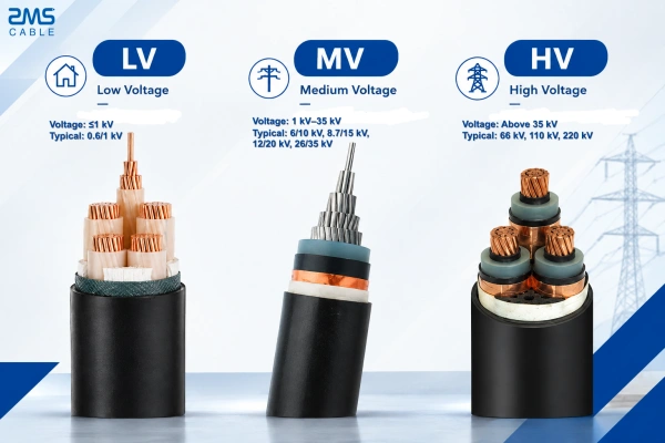
Principais diferenças entre LV / MV / Cabos de alta tensão
Baseado em padrões IEC, a tabela de comparação abaixo resume os parâmetros críticos para referência rápida:
| Item de comparação | Cabos BT | Cabos MT | Cabos de alta tensão |
|---|---|---|---|
| Tensão nominal | ≤1kV (principalmente 0.6/1 kV) | 1-35 kV | > 35 kV |
| Telas semicondutoras | Não obrigatório | Condutor obrigatório & telas de isolamento | Sistema de blindagem total de alta precisão obrigatório |
| Escudo Metálico | Opcional | Obrigatório (fita de cobre / fio de cobre) | Bainha metálica selada obrigatória |
| Teste de Descarga Parcial | Geralmente não é obrigatório | Teste de fábrica obrigatório | Descarga parcial rigorosa & testes de pré-condicionamento |
| Material de isolamento | PVC / XLPE | XLPE / RPE | XLPE espessado com bainha metálica bloqueadora de água |
| Uso típico | Distribuição de terminal para usuário final | Distribuição regional & coleta de energia renovável | Transmissão tronco de longa distância de grande capacidade |
| Padrão de Referência | CEI 60502-1 | CEI 60502-2 | CEI 60840, CEI 62067 |
Como selecionar cabos de alimentação adequados para o seu projeto
Aproveitando a prática de projetos no exterior, resumimos quatro critérios principais de seleção:
Combine a tensão nominal do sistema: A tensão nominal do cabo deve ser igual ou superior à tensão operacional do sistema. Nunca reduza a taxa de cabos. Para um sistema de 10kV, 0.6/1 Cabos kV LV não podem substituir produtos MT.
Ampacidade & cálculo da distância de transmissão: Escolha graus de tensão mais altos para circuitos de longo prazo para reduzir perdas I²R. Reduza a ampacidade para instalação diretamente enterrada ou colocação paralela de vários cabos.
Ambiente de instalação:
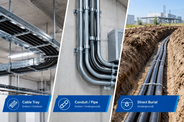
- Enterro direto ou dutos de cabos: Especifique a armadura (Armadura de fita de aço STA / Armadura de fio de aço SWA) para proteção mecânica.
- Túneis ou edifícios ocupados: Priorize as bainhas LSZH com baixo teor de fumaça e zero halogênio.
- Locais costeiros ou expostos a produtos químicos: Implante bainhas externas resistentes à corrosão.
Padrões de projeto & regras de aceitação: Confirme os padrões aplicáveis (CEI / Bobagem / ASTM etc.). Os requisitos estruturais e de teste variam e não podem ser trocados.
Nota de engenharia: O grau de tensão vem antes da seção transversal do condutor. Muitas especificações incorretas surgem do foco apenas no tamanho, ignorando os requisitos de blindagem e isolamento para os níveis de tensão alvo..
Informações necessárias para cotação de cabos de alimentação
Muitas rodadas de cotação se arrastam devido a especificações incompletas. Prepare os seguintes dados para agilizar as consultas:
- Norma aplicável ao projeto: CEI 60502-1 / CEI 60502-2 / Bobagem etc..
- Classificação de tensão: E.G.. 0.6/1 kV, 8.7/15 kV, 110 kV
- Material condutor, quantidade central & corte transversal: E.G.. 3×150+1×70mm² condutor de alumínio
- Requisito de armadura: Sem armadura / Armadura de fita de aço STA / Armadura de fio de aço SWA
- Tipo de bainha: PVC / Educação Física / LSZH, requisitos de resistência às intempéries ou anticorrosão
- Condição de trabalho: Enterrado diretamente / bandeja / duto; ambiente (costeira, baixa temperatura, exposição química)
- Comprimento total do pedido, comprimento do tambor por unidade, destino de entrega e prazo de entrega.
Exemplos de seleção de projetos
Caso1: Projeto de energia interna do complexo comercial do Sudeste Asiático
Todos os cabos passam em eletrocalhas dentro de edifícios ocupados sem enterramento direto. A tensão operacional do sistema é 0,4kV. 0.6/1 Cabos LSZH LV não blindados de kV foram selecionados, equilibrar custo e desempenho de segurança contra incêndio para distribuição de energia em terminais de edifícios.
Caso2: Circuito coletor solar em África
10 Circuitos de coleta local de kV, parcialmente enterrado diretamente em solo arenoso com risco de danos mecânicos. Recomendamos cabos de MT blindados XLPE com fita de aço de 8,7/15kV, atendendo aos requisitos de blindagem de campo elétrico e descarga parcial, ao mesmo tempo que resiste ao estresse mecânico subterrâneo.
Perguntas frequentes
1º trimestre: As telas semicondutoras podem ser removidas de Cabos MT para cortar custos?
Não. As telas semicondutoras são um componente obrigatório do cabo MT para homogeneização do campo elétrico. Removê-los provoca descarga parcial e falha prematura do isolamento, e cabos não serão aceitos em projetos internacionais.
2º trimestre: Fazer Cabos de alta tensão sempre entrega maior ampacidade para seção transversal igual?
Não. A ampacidade depende da seção transversal do condutor, modo de instalação e temperatura ambiente. Tensão mais alta reduz perdas na linha, mas não aumenta diretamente a capacidade de transporte de corrente.
3º trimestre: Pode blindado Cabos BT ser usados como cabos MT?
Absolutamente não. A armadura melhora apenas a proteção mecânica. Não pode substituir telas semicondutoras ou isolamento espesso. O isolamento de baixa tensão não suporta tensão elétrica de nível MT e irá falhar rapidamente.
4º trimestre: Condutores de cobre versus alumínio: como decidir?
O cobre oferece maior ampacidade e menor diâmetro externo. O alumínio é mais leve e mais econômico. Para circuitos de longa distância, condutores de alumínio com seção transversal única podem proporcionar economias substanciais nos custos totais do projeto.
Por que escolher cabos de alimentação ZMS?
Como fabricante de cabos que apoia empreiteiros globais de EPC no exterior, A ZMS fornece um portfólio completo de cabos de energia de BT e MT, com entrega de alta tensão por meio de recursos de parceiros qualificados.
Nossos produtos estão em conformidade com IEC, Bobagem, ASTM e outras normas internacionais. Cada cabo MT passa por testes de descarga parcial de fábrica 100%. Relatórios completos de testes de tipo e documentação de fábrica são fornecidos para apoiar licitações e inspeções de terceiros.
Armaduras personalizadas e configurações de bainhas especiais estão disponíveis para enterramento direto, corrosivo costeiro, Túnel LSZH e aplicações de baixa temperatura. Também podem ser fornecidas juntas e terminações de cabos correspondentes para minimizar riscos no local causados por incompatibilidades de acessórios.
Conclusão
Não há “melhor” absoluto entre LV, Cabos MT e HV. O princípio fundamental é corresponder à tensão nominal, distância de transmissão, ambiente de instalação e padrões de projeto. LV cuida da distribuição para o usuário final, MT atende redes de energia regionais, e HV suporta transmissão troncal de longa distância e grande capacidade.
Se você estiver trabalhando em infraestrutura no exterior, projetos de energia renovável ou de atualização da rede e precisam de ajuda com Cabo BT/MT/AT especificação ou preço, envie os parâmetros do seu projeto, condições do local e padrões aplicáveis. Nossa equipe técnica pode oferecer consultoria de seleção e cotações competitivas.